 Here is an overall view of the playfield
before I started the process. The picture doesn't show how beat up this playfield
was very well but it was a mess.
Here is an overall view of the playfield
before I started the process. The picture doesn't show how beat up this playfield
was very well but it was a mess. My Medieval Madness Restoration
The Acquisition
Because I'm so picky about my machines being in near perfect condition, Medieval Madness was no exception. When I was in the market to buy the machine, the only ones that seemed to be available were on the other side of the country. Plus they all carried $4,000+ price tags. Now since WMS has closed their pinball division doors, these machines have sold for as much as $11,000. I, like most people, hate buying pins sight unseen. So when I found a MM at a local arcade I had to jump on it.
This particular machine had obviously been on location its entire life. The playfield was beat (although no evident wear spots) and it looked like it hadn't been cleaned since day one. I knew that could all be fixed. One thing that usually cannot be fixed/replaced easily is the cabinet itself. This machine had a near perfect cabinet. There were no scratches, no drill holes, and the only thing keeping it from looking out of the box were a few small fingernail indentations around the flipper buttons. Barely noticeable so I could live with it.
I contacted the owner of the arcade inquiring about buying the machine. He was interested, the price was right, so the next week I picked it up and brought it home.
The following is pretty much a chronological account of what I did to restore this machine to NIB condition.
The Legs
Once I returned home with the machine, even before it was unloaded, I fully polished all four chrome legs which had been removed from the machine for transport. This was done by hand using Simoniz chrome polish. Both inside and outside of the legs were done. It's amazing what chrome polish can do. The legs looked like new when I was done. Good, one less thing (actually 4) to buy!
The Coin Door
I removed the coin door from the cabinet, fully disassembled it, then gave it a new coat of semi-gloss black paint. Even the mounting bolt heads received a new coat of paint. After sufficient drying time and, of course, cleaning the cabinet where the coin door had been, the coin door was re-installed.
The Cabinet
Before the legs were re-attached to the machine, I cleaned the corner areas of the cabinet where the legs had been mounted. There were also a few minor spots where the edges of the legs had cut through the artwork to the wood. I touched these up with a Sharpie marker. The legs were then re-attached and the machine finally unloaded from the truck.
I cleaned the exterior of the cabinet using Pledge. That's all that was needed.
The Backbox
I removed the translite lightbox from the backbox and disassembled it. All lightbulbs and flashers were replaced. Translite and backglass were cleaned on both sides. Lightbox was tested to ensure that all new bulbs were functioning properly then re-assembled.
The Playfield
Okay - this is gonna be a long one. I did manage to take some pictures along the way, so feel free to click on them for a larger view if you like.
Because I wanted this machine to look NIB when done, a playfield swap was necessary. I managed to go through 3 NOS playfields before I found one that was perfect. Two of those were the last ones WMS had in the warehouse, and they were unacceptably scratched.
Here's my strategy for doing a playfield swap -
1. Remove EVERYTHING from the original playfield until only the wired underplayfield components remain.
2. Clean eveything as it's removed.
3. Document EVERY piece removed, even if it's just a lamp, a rubber ring, or a nut/washer. Don't assume you'll remember it later. Trust me, you won't. I now take a digital picture of each item before it is removed for further reference.
2. Swap the wiring harness from old playfield to new playfield. This is done with all components left attached. I'll describe in more detail later.
3. Reverse the process from step 1. Since you've documented everything, just go back up the list!
Sounds easy enough, right? Only five steps, can't be too difficult. Actually, done correctly and patiently, the process is VERY enjoyable. Especially when you see that new playfield finally coming together. Alright, enough with the philosophizing - let's go to work!
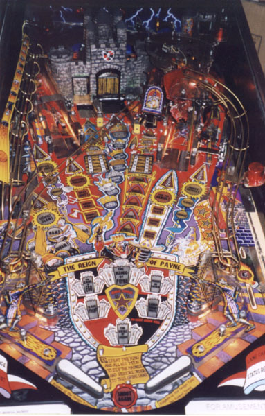
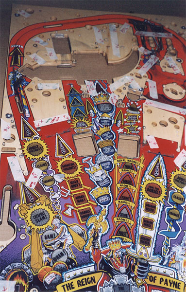
Here is an overall view of the playfield
before I started the process. The picture doesn't show how beat up this playfield
was very well but it was a mess.
 This picture shows the old playfield
partially stripped. I pretty much take the top-down approach to playfield stripping.
Remove the highest thing from the playfield and work your way down. If
something is in the way, remove it. And don't forget to document EVERYTHING.
I've made a text file of the steps I took to strip my
MM playfield. The original list was hand written. As you can see, I
document each piece and how many and what type nuts/bolts/screws were used for that piece.
This picture shows the old playfield
partially stripped. I pretty much take the top-down approach to playfield stripping.
Remove the highest thing from the playfield and work your way down. If
something is in the way, remove it. And don't forget to document EVERYTHING.
I've made a text file of the steps I took to strip my
MM playfield. The original list was hand written. As you can see, I
document each piece and how many and what type nuts/bolts/screws were used for that piece.
![]() Here is a view of the middle of the
playfield. You can see the wear around the troll flaps and the ramp entry. The
mylar around the troll flaps had lifted and dirt had made its way under it. Very
unsightly.
Here is a view of the middle of the
playfield. You can see the wear around the troll flaps and the ramp entry. The
mylar around the troll flaps had lifted and dirt had made its way under it. Very
unsightly.
 Here is a sort of 'before and after' shot of
the ramps. You can see how filthy this machine was. I cleaned all the plastics
and ramps with soap and warm water (taking MUCH care around anything electrical) then
polishing them with Novus. I ultimately ended up getting NOS ramps and an NOS
plastic set. The ramps had too much wear on them for my taste plus I got a great
deal on 'em anyway. There were also two broken plastics (not the slingshots).
Here is a sort of 'before and after' shot of
the ramps. You can see how filthy this machine was. I cleaned all the plastics
and ramps with soap and warm water (taking MUCH care around anything electrical) then
polishing them with Novus. I ultimately ended up getting NOS ramps and an NOS
plastic set. The ramps had too much wear on them for my taste plus I got a great
deal on 'em anyway. There were also two broken plastics (not the slingshots).
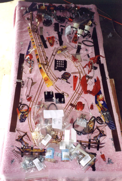 This is a table I had to put all the removed
parts on. I placed the removed parts plus any new parts to be installed on the
corresponding location on the table.
This is a table I had to put all the removed
parts on. I placed the removed parts plus any new parts to be installed on the
corresponding location on the table.
 Once all components had been removed from the
top side of the playfield, all that were left were wireforms and posts. As I removed
each post, I placed a piece of masking tape on the playfield and marked a letter code on
it with an arrow pointing to the hole it came from. I also labeled the
corresponding post/wireform with a second piece of tape.
Once all components had been removed from the
top side of the playfield, all that were left were wireforms and posts. As I removed
each post, I placed a piece of masking tape on the playfield and marked a letter code on
it with an arrow pointing to the hole it came from. I also labeled the
corresponding post/wireform with a second piece of tape.
I was now ready to remove the old playfield from the cabinet. To do this, I had to disconnect the wiring harness to the boards in the backbox. Again, as EACH connector was removed, it was labeled with the board location and orientation. After disconnecting everything to the playfield, the playfield was removed from the cabinet and brought into the house (the majority of the restoration took place in the garage).
I took a large packing blanket and placed it on a large open area of floor space. The new and old playfields were placed face down next to each other. Taking a tip from a fellow RGPer, this is how I swapped the wiring harness. (Using an NOS T-nut assembly playfield - if you have a blank NOS playfield, you'd probably want to move the T-nuts before you move the harness)
1. Remove each mounting screw from the old playfield and place it in the correct position on the new playfield. You only have to insert it about a half turn.
2. Once ALL the screws have been moved, move the wiring harness, in its entirety, to the new playfield. This will take a while as the screws in the new playfield may sometimes get in the way, but be patient, and everything will fall into place. Move small sections at a time so everything stays in its corresponding position. Another method I've used is to slide a large piece of cardboard under the entire harness. Then move the cardboard over the new playfield and just slide the cardboard out from under the harness.
3. Mount the components on the new playfield using the screws already in place.
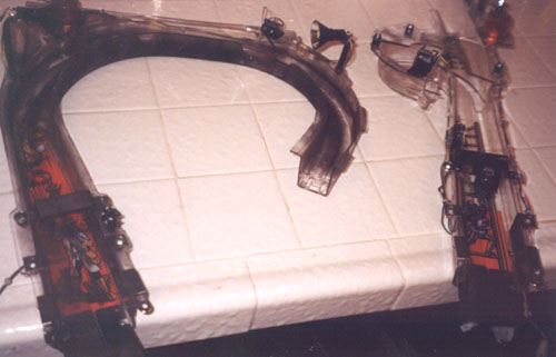
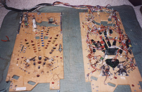 Here is a picture after I had moved the
harness to the new playfield. There are a few things that had to be moved
independently of the wiring harness like the playfield mounting slides and certain
solenoids. The pop bumper solenoids have studs into the playfield that had to be
moved to the new playfield, so that was done after the new playfield was back inside the
cabinet. Plus the new playfield was a T-nut assembly, so I didn't have to move those
too!
Here is a picture after I had moved the
harness to the new playfield. There are a few things that had to be moved
independently of the wiring harness like the playfield mounting slides and certain
solenoids. The pop bumper solenoids have studs into the playfield that had to be
moved to the new playfield, so that was done after the new playfield was back inside the
cabinet. Plus the new playfield was a T-nut assembly, so I didn't have to move those
too!
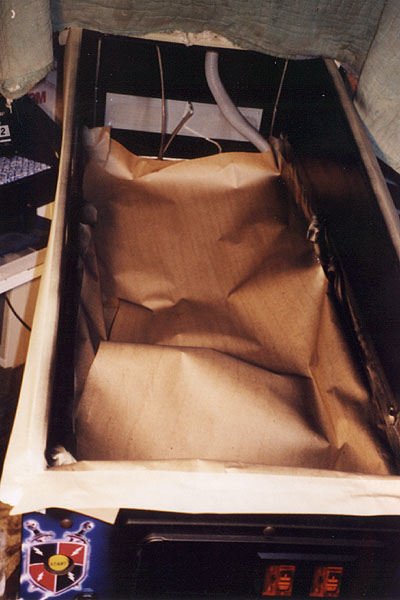 Speaking of the cabinet, the interior walls
of the cabinet had become scratched and dulled. While I had the old playfield out of
the machine, I masked the cabinet and gave it a few coats of gloss black paint. Hey,
if it's gonna look NIB, even these details matter (I told you I was picky!).
Speaking of the cabinet, the interior walls
of the cabinet had become scratched and dulled. While I had the old playfield out of
the machine, I masked the cabinet and gave it a few coats of gloss black paint. Hey,
if it's gonna look NIB, even these details matter (I told you I was picky!).
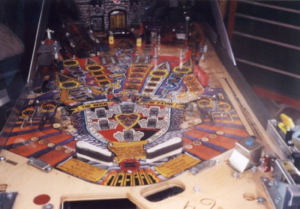
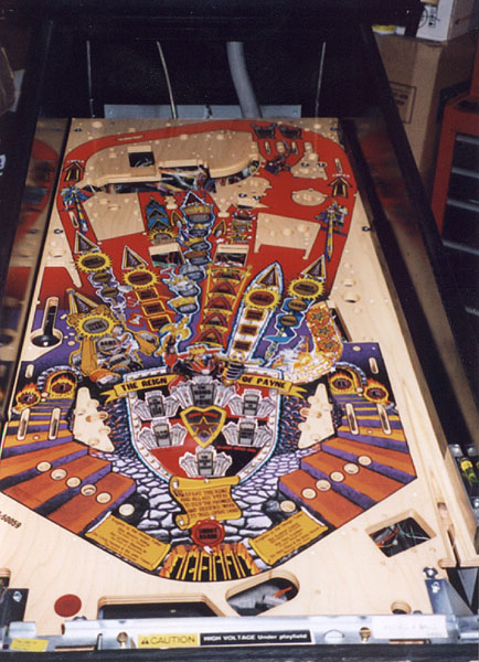 Now with the cabinet freshly painted and the
playfield harness swap done, the new playfield was placed back into the cabinet.
This is the point where it really becomes worthwhile. Seeing that brand spankin' new
playfield in the machine really inspires you to finish the job. I you ever wished
you hadn't started, this is the point you're glad you did! Did you notice the
glass-like reflections on the inside of the cabinet? The repainting really made a
difference!
Now with the cabinet freshly painted and the
playfield harness swap done, the new playfield was placed back into the cabinet.
This is the point where it really becomes worthwhile. Seeing that brand spankin' new
playfield in the machine really inspires you to finish the job. I you ever wished
you hadn't started, this is the point you're glad you did! Did you notice the
glass-like reflections on the inside of the cabinet? The repainting really made a
difference!
Everything was now pretty much reassembled in the reverse order of removal. During this process is where I had the joy of experiencing the 'exploding tempered glass' phenomena (luckily not ON the machine), which was promptly discussed on RGP! Oh well, guess with everything else I did, might as well get a new playfield glass!
Here is a list of items I replaced with NOS parts -
When everything was finally completed, I ran through all the tests the machine had to offer. All lamps and flashers, switches, optos, drawbridge, etc. I did have one minor 'oops' - when soldering one of the new slingshot switches, I accidentally dropped solder on the opto board mounted on the underside of the playfield. Didn't notice until I powered up the machine and half the optos wouldn't work. Luckily replacing the driver chips and removing the offending blob of solder cured that problem.
Total time spent on this project? Probably 40-50 hours. Was it worth it? Without a doubt!